
“Leak” is one word doing three different jobs.
Ask a data center operator what worries them most about liquid cooling, and the word “leak” is likely to be near the top of the list. Ask the next question—“Which kind of leak?”—and the conversation often stalls. The industry still tends to treat them as one risk.
They are not. They are discovered at different times, solved in different ways, and—most importantly—owned by different parties. Treating them as one problem concentrates attention and budget in the middle, while leaving both ends thin.
One boundary condition before we begin: this is not a mutually exclusive classification by leak location. A connector can leak on day one or in year three. Corrosion can eventually perforate a cold plate or a pipe. I am classifying leaks by the three windows in which risk most commonly reveals itself: manufacturing, delivery, and service life. Each window creates a different evidence trail, a different accountable party, and a different cost owner.
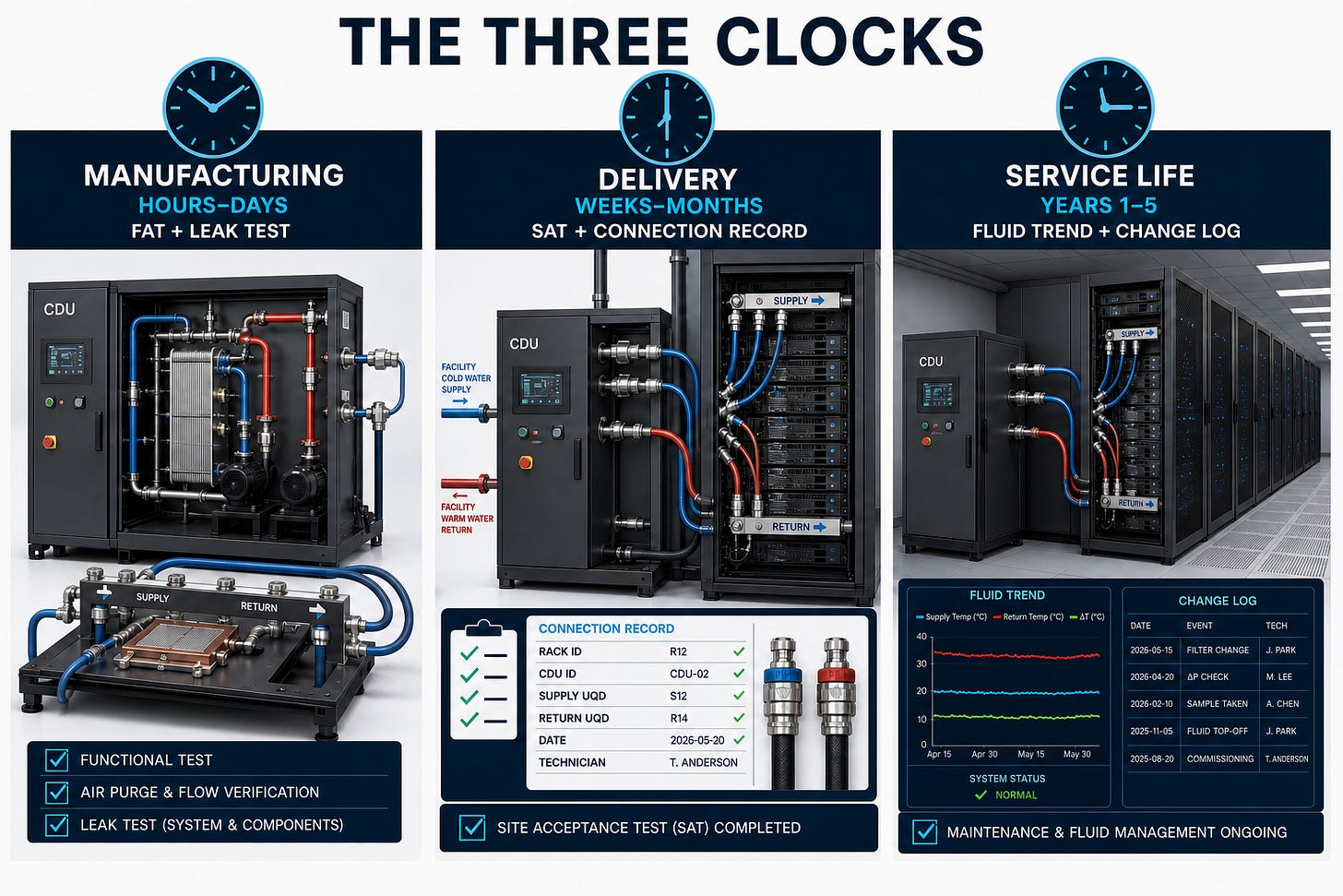
Clock One: Manufacturing
Welds, brazed joints, crimps, and assembly defects | Hours to days | Should be found in the factory
Immersion and cold-plate systems both contain metal boundaries that have been joined together. Cold plates are brazed or friction-stir welded. Manifolds are welded. Skids and CDUs contain welded assemblies. Hoses are crimped. Every newly created fluid boundary gives a defect somewhere to survive: porosity, lack of fusion, inclusions, or microcracks in a weld; voids or incomplete wetting in a brazed joint; eccentricity or springback in a crimp.
These defects may be invisible to the eye. A visual water check or a short pressure-decay test with inadequate resolution may miss them too.
This is the crudest clock, but it is also the one with the most mature methods. Automotive and refrigeration manufacturers have used these tools for decades. The unresolved issue is not technology. It is process discipline.
Five things that work
1. Define the allowable leak rate before choosing the method.
More sensitivity is not automatically better. First define the allowable leak rate. Only then can you specify the test medium, pressure, stabilization time, hold time, temperature compensation, instrument resolution, and reject threshold. Asking “helium or pressure decay?” before defining the target turns a process question into an equipment-purchasing question.
2. Match the method to the target.
Pressure decay is fast and inexpensive. It is perfectly adequate for gross leaks. It is not sufficient for every small leak. For tighter limits, use a tracer-gas method matched to the requirement: helium with a mass-spectrometer leak detector, or forming gas—typically a low-concentration hydrogen/nitrogen blend—with a dedicated hydrogen detector. A micropore that passes an immersion (bubble) test may become visible under a properly specified tracer-gas test.
3. Test the assembly, not just the parts.
A cold plate that passed component test says nothing about the manifold welded into the next assembly, or the transition fitting between them. Any operation that creates a new fluid boundary—welding, brazing, crimping, threaded or flanged assembly, or quick-disconnect installation—should be followed by a leak test with a clearly defined test boundary.
OCP system-level guidance explicitly identifies joints, connectors, and piping as pressure/leak-test targets. It cites 1.5 times design pressure as a reference test pressure, while also stating that the final value must be agreed between the manufacturer and end user. It is a reference, not a universal number to copy into every specification.
4. The last factory test is not the last test.
Shipping and rigging impose loads. A system that passed FAT is not automatically still leak-tight after transport. It needs another clearly bounded verification after arrival and before first fill.
5. Turn the test record into a digital thread.
“Pressure-tested” is not an insurable record. The record should include the serial number, test boundary, test medium, pressure, stabilization and hold times, ambient and fluid temperatures, instrument resolution and calibration status, allowable leak rate, result, operator, and any retest after repair.
This clock matters because it is the only one where failure is still cheap. Find a porous weld on a test stand and the cost is a fitting. Find the same defect beneath an energized rack and the cost is a data hall incident.
Clock Two: Delivery
Quick disconnects, hoses, valves, and field connections | Weeks to months | Commissioning or the first year
Public design guidance treats connections, hoses, valves, and quick disconnects as high-attention leak points. A continuous pipe run is usually not the first suspect, but corrosion, wear, freeze-thaw exposure, or external force can still make the pipe itself fail. The accurate claim is not “pipes do not leak.” It is that connections deserve the first look.
Connection counts rise quickly. In a direct-to-chip rack, every compute tray needs a supply and return interface. Add rack headers, CDU connections, valves, sensor ports, and drain points, and the total can quickly reach dozens or more than one hundred interfaces. Count carefully: connector ends, mated pairs, and serviceable connections are not the same metric.
This is the clock the industry watches most closely—and rightly so. But too much attention goes into selecting components, while a large share of risk is created by assembly and process.
Six things that work
1. Reduce the number of field-made connections.
It is the highest-leverage and least glamorous move. Every additional serviceable connection creates another opportunity that must be designed, assembled, verified, and maintained. The probabilities are not identical—connector type, location, assembly process, and detectability matter—but the direction is clear. A factory-integrated assembly has a known connection count and arrives with a test record. A field-built loop often has neither.
2. Standardize quick disconnects, but do not confuse “standardized” with “leak-proof.”
OCP UQD and UQDB specifications define interchangeability, pressure and temperature ranges, flow, and maximum fluid loss during mating and unmating. That reduces custom interface risk. It does not qualify the hose termination, crimp, or field assembly around the connector. Do not cite a generic “rated number of cycles.” Require the supplier’s actual cycle-life data, define the allowed cycle count for the project, and specify end-of-life performance.
3. Understand the counterintuitive disconnection risk.
The OCP/Vertiv leak-detection white paper notes that a quick disconnect can have a higher probability of leakage during disconnection than a fixed connector because contamination can hold the valve open. That links initial flushing directly to connector protection. Commissioning debris is not merely dirty. It can stop a valve from closing.
4. Flush with temporary equipment, never the production CDU.
The first flush is intended to remove construction debris. Sending that debris through the machine you are about to depend on creates a debt that will be repaid later. Flushing also needs acceptance criteria: a temporary flush cart, bypass filtration, sampling points, differential-pressure trends, and particle/cleanliness limits. Only after acceptance should the production CDU and IT loop be connected.
5. Elastomers matter, but they are not the only suspects.
Seal compatibility and life are critical. So are a contaminated valve, a poor crimp, hose fatigue, and assembly side-load. Do not compress the entire risk model into one O-ring.
6. If multiple platforms must share a loop, write the boundaries first.
Different hardware has different pressure drops, flow requirements, temperature bands, and fluid specifications. The first symptom may not be a leak; it may be flow imbalance and an argument over which vendor’s specification governs. But that ambiguity sits upstream of leak risk.
Clock Three: Service Life
Materials, fluid chemistry, cycling, and control drift | Years one to five | Often discovered by accident
This is the hardest clock to price and insure. Liquid cooling itself is not new. What is new is the combination of power, flow, interface count, and operating temperature in current AI racks. Public multi-year field data for that combination remains limited.
The uncomfortable property of this clock is that everything can be compliant on day zero. The new connector is tight. The seal is elastic. The loop is clean. Three months later it may still look fine. These failures are not necessarily manufactured into the system. They are accumulated.
Vibration, thermal cycling, and sustained mechanical load change a connection over time. Pumps rotate. Coolant moves. Racks “breathe” as workload changes. The OCP/Vertiv white paper includes a case from a national laboratory: a suspended hose imposed sustained side-load on a fitting, leading to seal fatigue. The corrective action was not a better seal. The hose was rerouted vertically and supported to remove the continuous lateral load. The solution was in the installation, not the component.
Mixed metals do what mixed metals do. Copper cold plates, stainless manifolds, aluminum heat exchangers, and brass fittings can create galvanic couples in one wetted loop. But corrosion cannot be predicted from a galvanic-series chart alone. Material pairing, area ratio, temperature, fluid chemistry, dissolved oxygen, velocity, and inhibitor formulation all matter. The right unit of validation is the complete wetted-material combination, not an isolated qualified part.
Coolant chemistry has a service life. Inhibitors are consumed. pH drifts. Glycol oxidizes. The fluid may still look exactly as it did on day one. Appearance is not analysis.
Low-flow regions accumulate problems. Dead legs, idle branches, and standby loops that never circulate are more vulnerable to deposits, local chemistry changes, and microbiological risk. They are also the places least likely to be instrumented.
Five things that work
1. Build a wetted-material bill of materials.
Record every metal, elastomer, and plastic, together with the supplier. When a fluid analysis turns abnormal, that document is the difference between diagnosis and guessing.
2. Sample by trend, not suspicion.
The interval should be set by the coolant supplier, OEM, system volume, material combination, operating temperature, and risk. Sample more frequently during initial operation, then widen the interval once the system is stable. The essential controls are a startup baseline, fixed sample points, consistent methods, alarm thresholds, and a trend history. Depending on fluid type, parameters may include pH, conductivity or resistivity, glycol concentration or refractive index, inhibitor reserve, dissolved metals, particles and turbidity, microbiological indicators, color and odor, and filter differential pressure.
3. Put connection condition into OEM-defined preventive maintenance.
Inspect visible seepage, supports and strain, hose wear, vibration, and valve condition. Do not blindly retighten connections. On many seal designs, retightening can damage the seal or violate the OEM procedure. Verify torque only when the manufacturer provides a method and value.
4. Eliminate dead legs during design.
Give standby branches a flushable and drainable path, and place sample points where they cover the worst-case location.
5. Capture the commissioning baseline while you still can.
Record branch flow, rack pressure drop, temperature distribution, and the startup fluid sample. Two years later, “drift” only exists relative to a baseline someone bothered to keep.
Condensation: the “leak” that never leaked
Condensation belongs outside the three clocks because it can appear on the first day of commissioning. When coolant supply temperature falls below the local dew point, water appears on a surface whose fluid boundary was never breached. The electrical consequence can look identical to a leak, while the root cause is humidity, insulation, or a control setpoint.
The control system should maintain a designed dew-point margin—not zero margin—and define a conservative fallback when a dew-point or humidity sensor fails. Insulation and vapor barriers must remain intact, with suitable sensor redundancy. A leak rope cannot distinguish condensation from a real coolant leak on its own; dew point and surface temperature must be correlated.
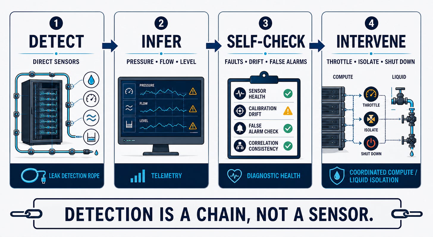
Detection Is Not a Sensor. It Is a Chain from Discovery to Isolation.
Treating leak detection as “installing a few sensors” is one of the most common simplifications in this field. Public guidance points to four layers.
Layer one: direct detection. Leak ropes, spot detectors, and floats belong beneath cold plates and hoses, near quick disconnects and manifolds, at the bottom of racks, in CDU drip trays, beneath raised floors, and in containment pans. The rule is simple: put the sensor where liquid will actually travel and pool, not where it looks symmetrical on a drawing.
Conductive direct detection has a hard boundary: the fluid must reach the sensor in sufficient quantity and must be conductive enough to trigger it. It works for water-based or sufficiently conductive fluids, but not automatically for dielectric liquids, refrigerants, or every coolant formulation. Those systems may require optical sensing, mass balance, pressure/flow algorithms, or refrigerant-specific detection. One sensor technology does not cover every liquid-cooling architecture.
Layer two: indirect detection. Use pump and loop pressure differential, reservoir level and makeup volume, supply/return mass balance, branch-flow imbalance, and abnormal pressure loss. These signals may identify a problem before a direct sensor becomes wet—but the logic must distinguish venting, thermal expansion, planned makeup, and an actual leak, or it will produce noise.
Layer three: sensor self-diagnostics. Open circuits, shorts, contamination, incomplete drying, condensation, and drift can create false negatives or false positives. “Sensor fault” must itself be a reportable state, not a silent blank. Thresholds set too aggressively also create alarm fatigue. Eventually the signal that matters is ignored with the rest. Sensitivity must be commissioned against the real installation.
Layer four: graded intervention. First comes notification and manual action: alarm, locate, then close the upstream and downstream valves under an approved procedure. A single manual shutoff valve is inexpensive and low-loss, but isolates only one side of the fluid network. Isolating a segment requires correctly placed valves and sequential human action.
The second level is automatic fluid intervention through rack-, manifold-, or CDU-level isolation valves. Full-port interlocking ball valves can minimize normal pressure loss, but add cost and mechanical complexity.
The third level coordinates compute and fluid response. The BMC throttles or performs a controlled shutdown of affected equipment while the fluid segment is isolated, and the remaining system is verified to retain adequate flow. A dry-break quick disconnect addresses fluid loss during maintenance disconnection. It is a preventive design feature, not a substitute for post-alarm isolation.
A CDU shutdown cannot be reduced to “stop the pumps.” OCP/Vertiv guidance notes that a rapid reduction or loss of flow in a cold plate can allow full-power chips to boil local coolant and create overpressure. Thermal throttling and thermal protection must be enabled on cold-plate-cooled devices, and the sequence among compute throttling or shutdown, pump shutdown, and fluid isolation must be validated under transient conditions.
Most importantly, test the entire sequence during commissioning using the specified test fluid or controlled simulated signals. An automatic isolation logic that has never been triggered is not protection. It is an assumption.
NVIDIA’s Mission Control management framework for GB200/GB300 NVL72 already exposes rack electrical-isolation status, rack liquid-isolation status, the number of devices reporting leaks, and device-level cold-plate, manifold, and leak-detection-system states. In NVIDIA’s official example, nodes affected by a large leak enter DOWN status carrying a leak:large marker. A leak is no longer just a facilities alarm. It is a system event that enters compute-availability management.
Detection alone is no longer enough. Isolation status is becoming part of the evidence that must be delivered.
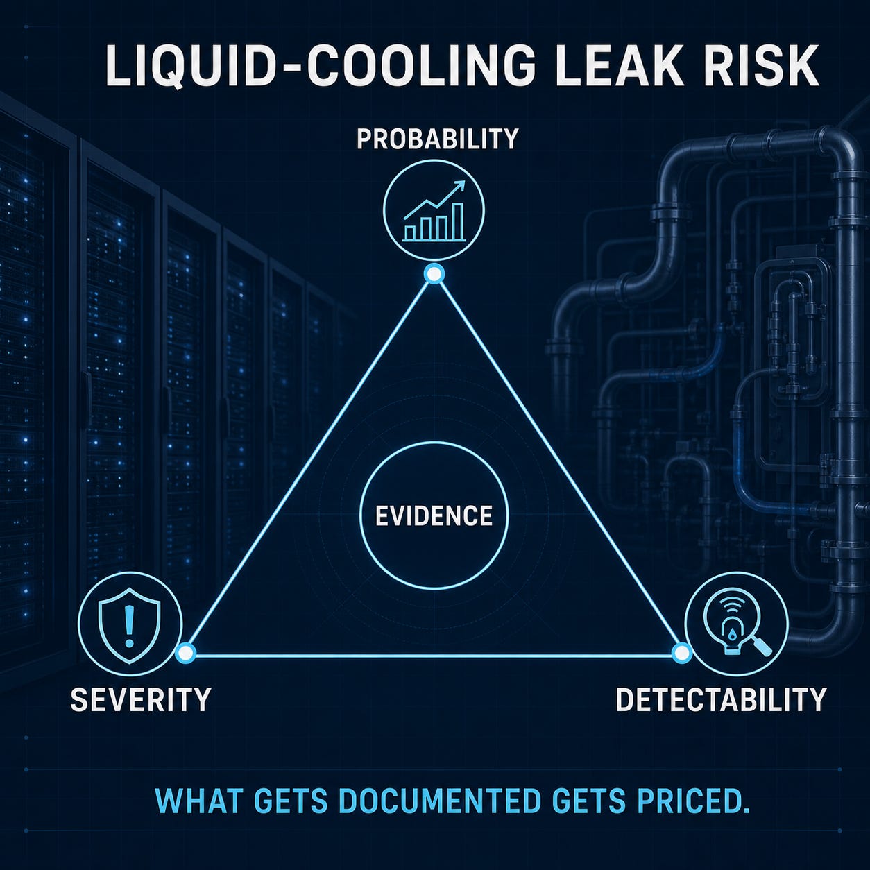
From Two Buckets to Three Risk Factors
I used to say, “Detection buys severity; occurrence is controlled elsewhere.” The direction was right, but incomplete. Public risk frameworks use three factors: probability, severity, and detectability.
The more accurate statement is:
Detection mainly compresses the time from occurrence to isolation. It improves consequence and detectability, but it cannot erase an assembly defect that already exists. Probability is shaped more by connection count, connection method, material compatibility, manufacturing, and installation.
Insurance must price the combination of all three. A sensor is not the whole answer.
There is one number I would like to know, and almost no one can provide it: Was the connector that failed made in the field, or factory-assembled and pressure-tested? Operators usually report that “it leaked,” not what kind of connection it was. This is not a proven conclusion. It is a field insurers should begin collecting. Once they do, the economics of the second clock will change immediately.
Evidence from a Different Operating Environment
Before delivering cold-plate systems, I spent years on the immersion side. Immersion accelerates the third clock. The mechanisms cannot be copied directly into a cold-plate loop, but the lesson carries.
I watched two failures in fleets operating around 60°C. In the first, boards that were normal at installation suffered gradual thermal-interface failure within days. It was not a manufacturing defect or a design error. The interface simply had no obligation to remain where it had been placed. The project was corrected by adding a validated surface-protection process that had previously been treated as optional.
In the second, one hardware generation developed deformed and detached capacitors in the immersion fluid. The capacitor casing material had never been validated for that environment, while the rest of the board was unaffected. That hardware generation was removed from immersion service.
Neither event was a coolant leak. They support a more fundamental point: material compatibility must be validated under representative accelerated-aging conditions, not inferred from individual component data sheets.
A property measured on day zero is a dated measurement, not an immutable property of the component.
A validation report that characterizes only a new assembly describes the easiest day of its life.
The Three Clocks at a Glance
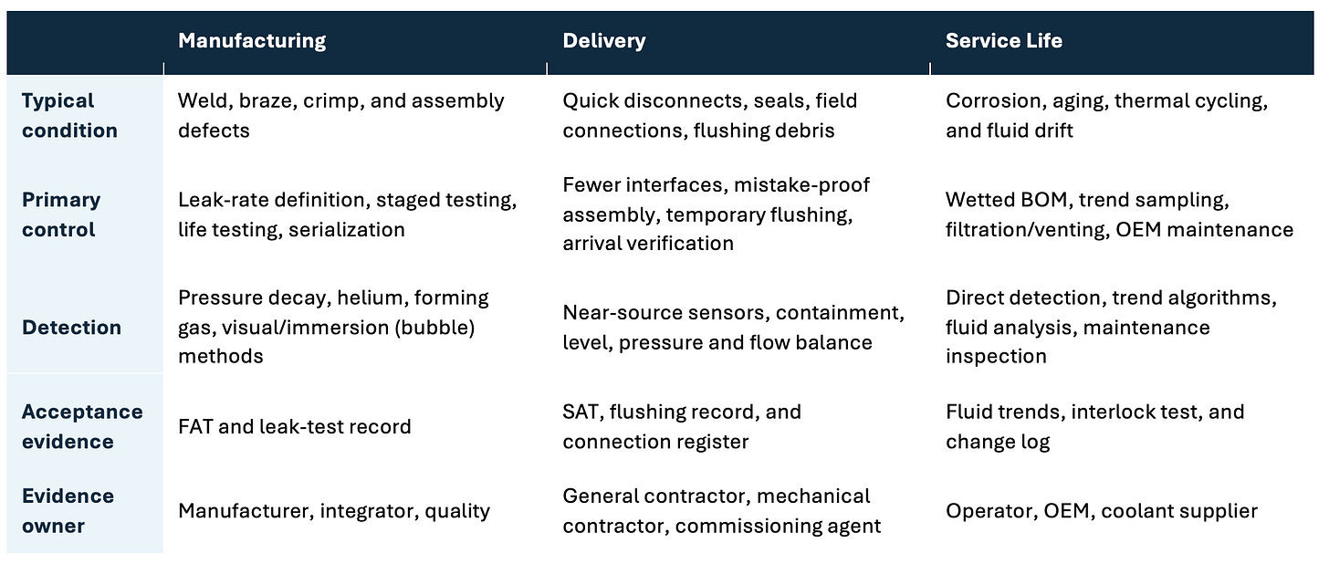
Separate category—condensation: coolant below local dew point, damaged insulation, or sensor/control failure → dew-point margin, interlock, vapor barrier, redundancy, and conservative fallback → correlate leak sensing with dew point and surface temperature.
What This Article Is Really About
Three clocks. Three bodies of evidence.
Manufacturing evidence: test boundary, serial number, allowable leak rate, method, pressure, time, temperature, result, and post-repair retest.
Delivery evidence: connection register, connection type and location, assembler and tooling, post-transport and pre-fill verification, and flushing acceptance criteria.
Operating evidence: startup fluid sample, wetted-material BOM, sampling and makeup history, pressure/flow/level trends, alarm and automatic-isolation test record, and maintenance/change log.
None of this is exotic. All of it can be produced. Yet in the projects I see, money and attention remain concentrated on the second clock, while evidence from all three is rarely packaged in a form that can be priced.
That last phrase is the point. The economics of liquid cooling are moving toward insurance, and insurance runs on evidence. An underwriter can price a bounded pressure-test record, a connection register, a fluid-analysis trend, and an interlock-test record. An underwriter cannot price “the work was done carefully,” even when it is true.
You can price a document. You cannot price craftsmanship.
For anyone planning a liquid-cooled data hall in the next eighteen months, the right question is no longer, “Did we install leak sensors?”
It is:
What evidence did we preserve for each clock—manufacturing, delivery, and service life?
And after an alarm, who has the authority to shut which fluid segment and which compute nodes, within how many seconds?
— Jim Li, founder of NextGenergy, focuses on power, cooling, and energy reuse for AI compute infrastructure. He is working to move next-generation AI data centers beyond single-point equipment optimization toward integrated system design across power, liquid cooling, and heat recovery.
Public references include:
[OCP/Vertiv, “Leak Detection and Intervention”](https://www.opencompute.org/documents/acs-cold-plate-leak-detection-and-intervention-white-paper-pdf-1); [OCP, “ACS Liquid Cooling Cold Plate Requirements”](https://www.opencompute.org/documents/ocp-acs-liquid-cooling-cold-plate-requirements-pdf); [OCP, “OAI System Liquid Cooling Guidelines”](https://www.opencompute.org/documents/oai-system-liquid-cooling-guidelines-in-ocp-template-mar-3-2023-update-pdf); [OCP, “Universal Quick Disconnect Specification”](https://www.opencompute.org/documents/ocp-universal-quick-disconnect-uqd-specification-rev-1-0-2-pdf); [OCP, “Cold Plate Development and Qualification”](https://www.opencompute.org/documents/ocp-cold-plate-development-and-qualification-with-integrated-comments-pdf); and [NVIDIA, “Mission Control Software Administration Guide—Leak Detection”](https://docs.nvidia.com/mission-control/docs/systems-administration-guide/2.3.0/leak-detection.html).
By Jim Li, founder of NextGenergy. First published on Substack. Discuss it there or on LinkedIn. Markdown version.